ethernet werking
The first Ethernet networks were built using coaxial cable. Such a network has a bus-topology: everyone is connected to the same bus — in this case, the coax cable.
In practice, this meant:
- “Thick coax” RG-8/U in Ethernet 10BASE5, also called thicknet (1980)
- “Regular coax” RG58/U in Ethernet 10BASE2, also called thinnet (1985)
These networks have since been replaced by switched networks with a star or tree topology. However, because Ethernet must remain compatible with thicknet and thinnet, it still uses the 40‑year‑old CSMA/CD protocol. Its principles are best explained with the old bus topology in mind.
CSMA/CD stands for- CS: Carrier sense (listen and wait until the bus is not in use — idle)
- MA: Multiple Access (several hosts share the medium, taking turns)
- CD: Collision detection (two hosts transmit at the same time,
detect the collision quickly, and a back‑off algorithm gives one of them priority)
- Listening: CARRIER SENSE
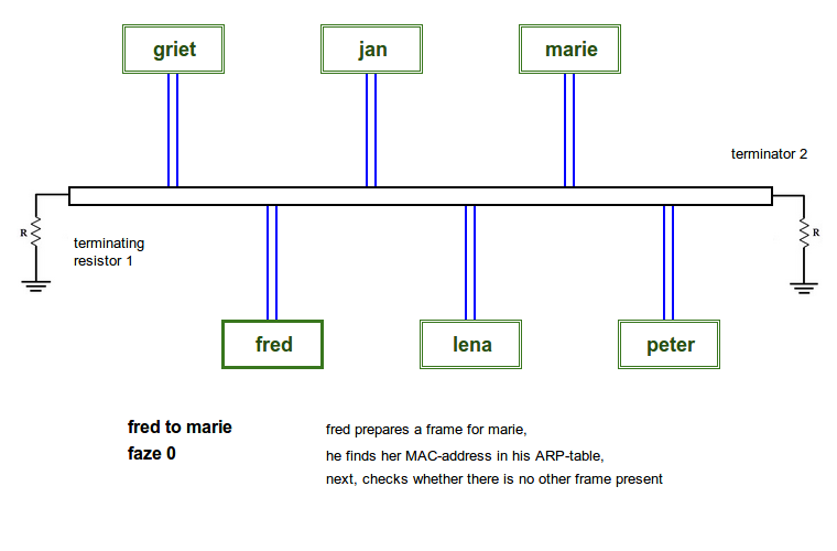
In phase 0, the sender — FRED — first looks up the MAC address of the destination, MARIE, in his ARP table. We assume this address is available.
(You can display the ARP table with the command:C:\> arp -a)
Next, the payload from the higher (network) layer is wrapped in the correct frame elements and prepared for transmission.
FRED now listens to the medium (the cable).
If the line is silent, the frame can be sent.
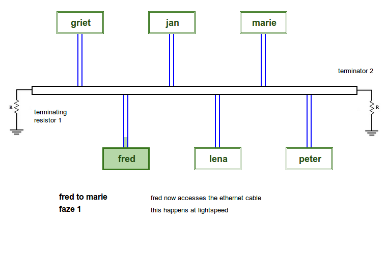
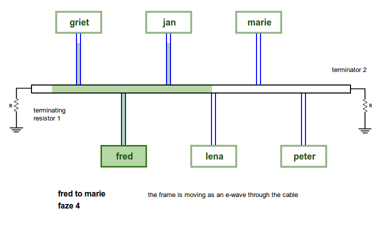
- Access: MULTIPLE ACCESS
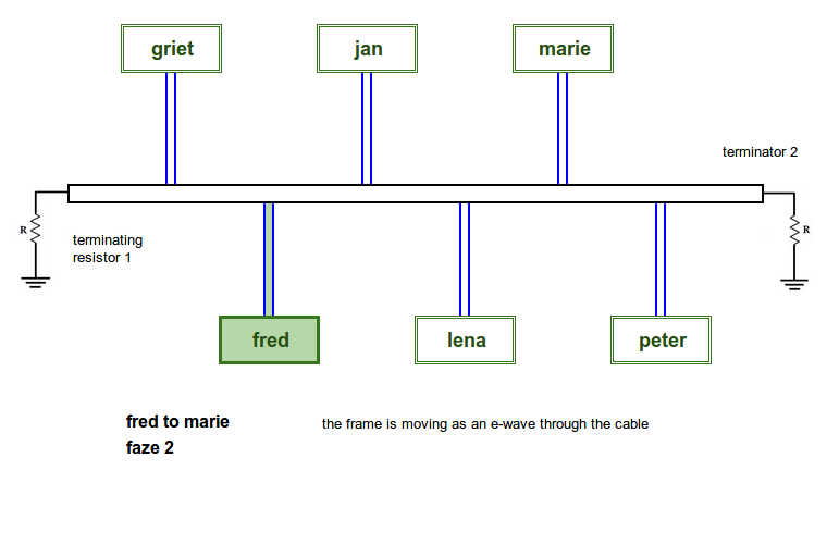
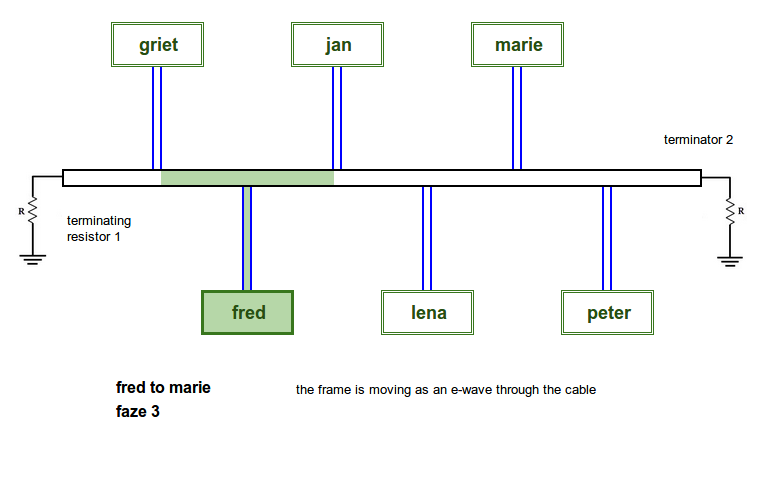
In phases 1 to 4, we see FRED’s frame entering the cable. It travels at roughly 200,000 km/s in copper wire. The frame rushes forward in all directions like a wavefront.
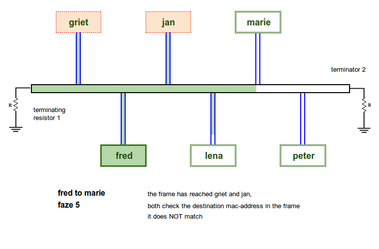
- Reception by everyone
In phase 5 and onward, because of the bus topology, FRED’s frame reaches every host.
The first field of the frame is the destination address, in this case MARIE’s.
Each participant checks whether the destination address matches its own.
If not, the packet is simply dropped (not processed).
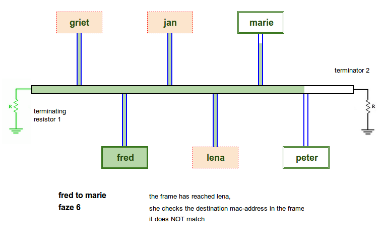
- 2 terminators
In phase 6 and onward:
High‑frequency signals tend to reflect back into the cable at its physical ends.
These reflections mix with the useful signal and make everything unreadable.
To prevent this, two terminators are attached at the ends of the coax cable.
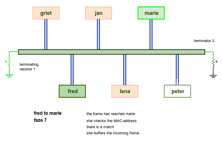
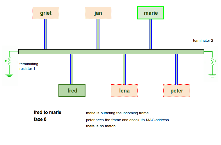
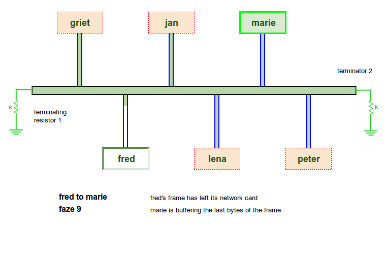
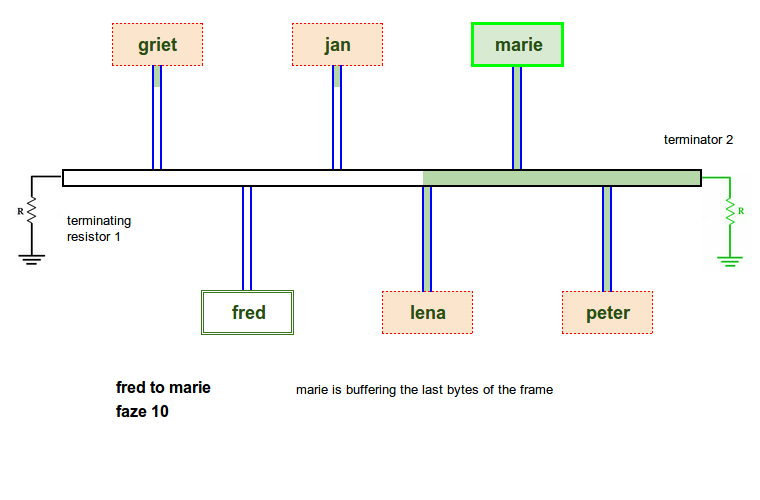
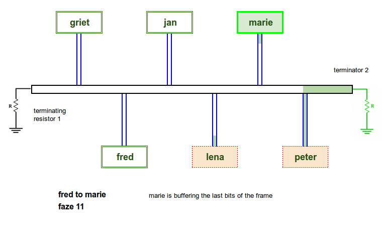
- Reception by everyone, including the destination
In phases 7 to 11, the frame reaches the correct destination.
Upon recognizing its own MAC address, MARIE buffers the frame (stores it in memory until fully received).
- Processing the frame
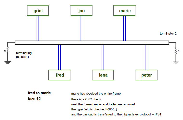
In phase 12, the frame has fully arrived at MARIE.
She recalculates the CRC at the end of the frame and compares it.
If transmission errors occurred, the mismatch would reveal them now.
In our example, the CRC is correct.
Next, the TYPE field is examined to determine which higher‑layer protocol should take over.
If the type is 0800x, the frame header and trailer are removed, and the payload is passed to the network layer: IPv4.